Fully insulated ring network switchgear

RolinkPower ™ fully insulated intelligent ring network cabinet covers SF6 gas insulation series, solid insulation series, and environmental protection gas insulation series, And equipped with RolinkPower ™‘s intelligent power Internet of Things system truly establishes the power digital ecology of "unattended and attended".

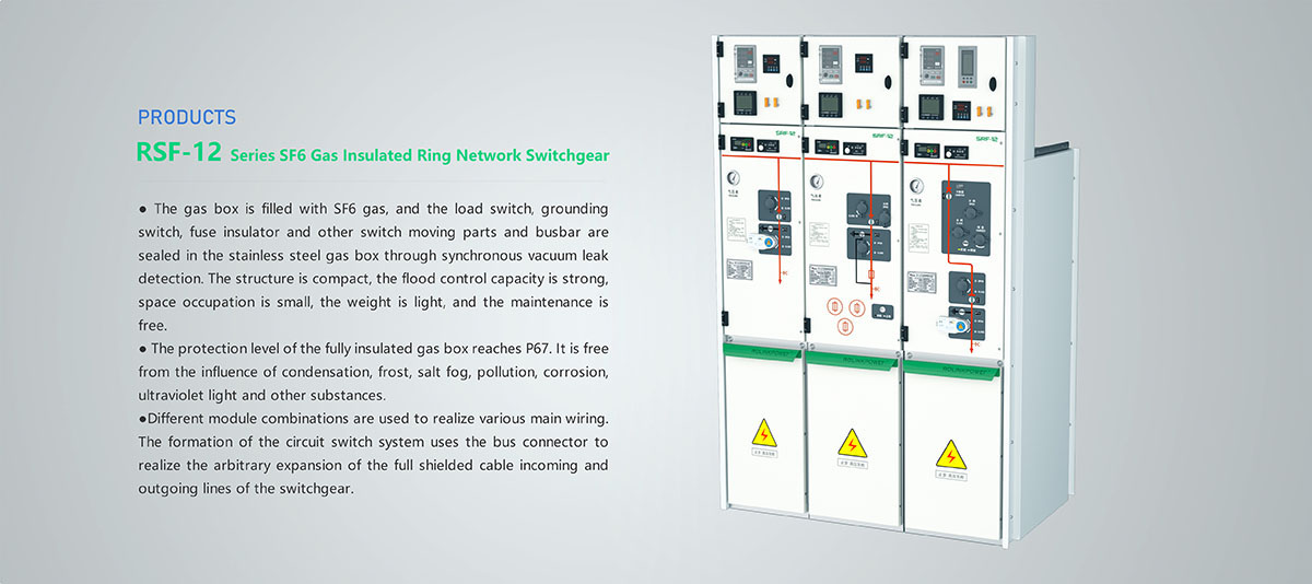
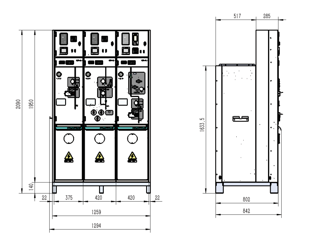
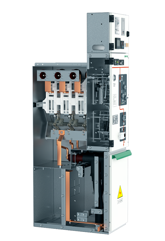
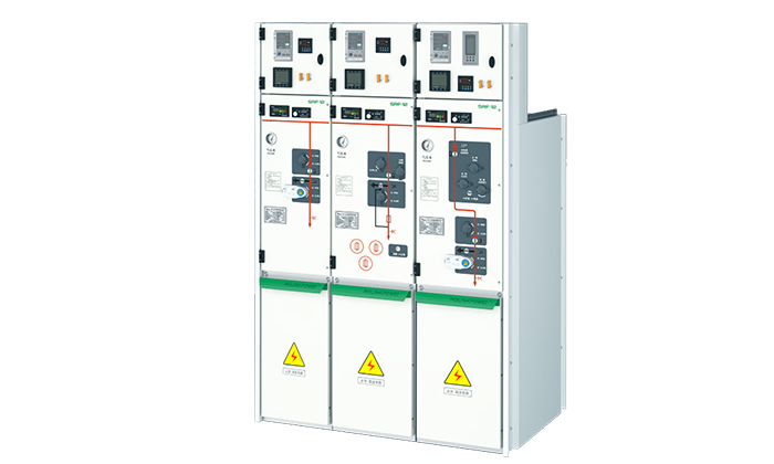
RSF-12 Gas insulated ring network switchgear

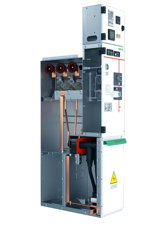
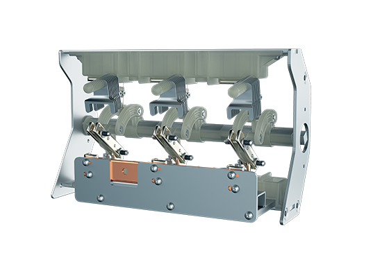
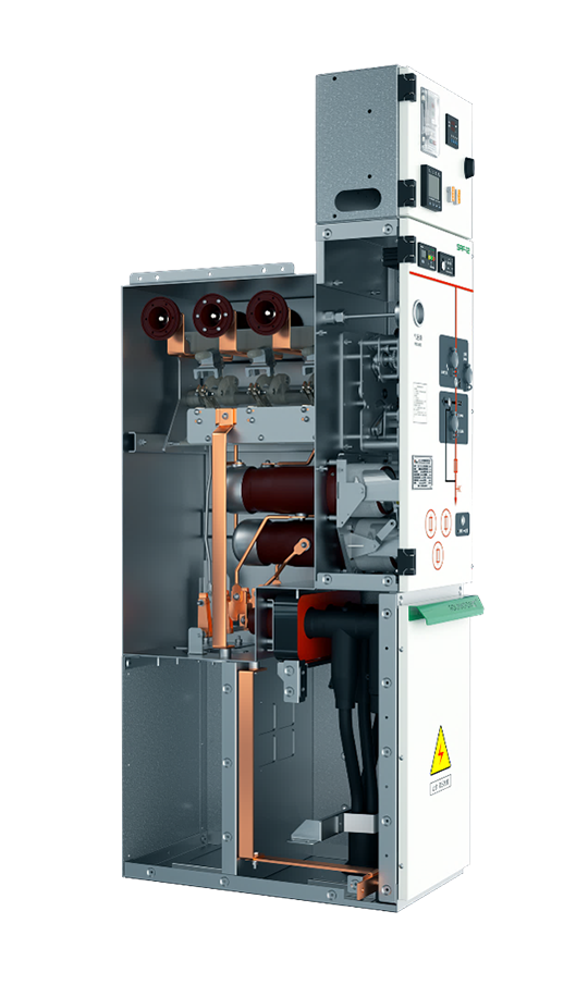
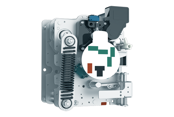
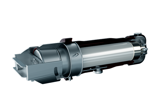
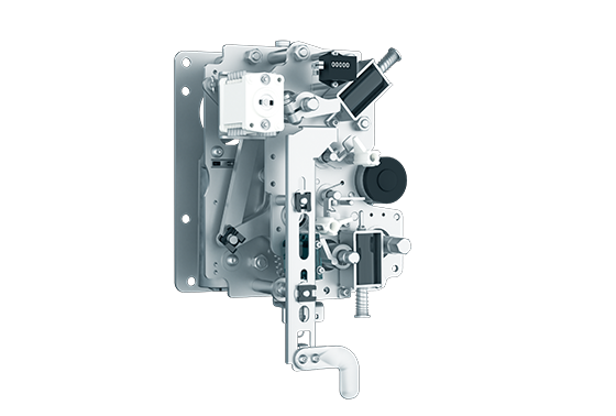
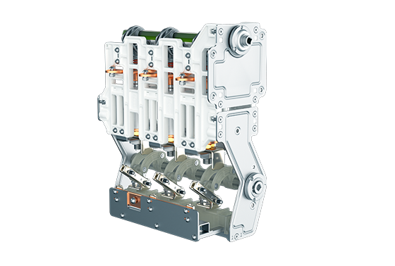
The air box of RSF-12 series aeration switchgear adopts high-quality 3mm thick stainless steel shell. The stainless steel plate is formed by laser cutting and automatically welded by an advanced welding manipulator to ensure the air tightness of the air box. SF6 gas filled in the gas box is vacuumized synchronously for leak detection; The load switch, grounding switch, fuse insulating cylinder and other switch moving parts and bus bars are all sealed in the stainless steel gas box, and the protection grade of the gas filled housing reached IP67.

It shall not be affected by the environment, and shall be resistant to condensation, frost, salt fog, pollution, corrosion, ultraviolet and chemical substances;

All high-voltage live parts and switching elements are sealed in the stainless steel box filled with SF6 gas, with compact structure, small space occupation, light weight and full insulation;

Modular design, with different module combinations to realize various bus bars and form a loop switch system;

Silicone rubber connector is adopted to realize the plugging of high-voltage components and the arbitrary expansion of the switchgear; Incoming and outgoing lines of fully shielded cables; Vacuum circuit breaker switchgear can be used;

High voltage monitoring element and integrated digital relay can be used; High voltage metering switchgear can be equipped; Remote control and monitoring unit can be added;

Over current relay protection device can be installed; Strong flood control capability, long service life, maintenance free, and low operation cost; Meet the requirements of distribution network automation upgrade.

Load switch unit and load switch combination unit Circuit breaker unit
Load switch Combination Vacuum switch Isolating/grounding switch
Rated voltage kV 12/24 12/24 12/24 12/24
Power frequency withstand voltage kV 42/65 42/65 42/65 42/65
Lightning impulse withstand voltage kV 75/125 75/125 75/125 75/125
Rated current A 630/630 Note[1] 630/630
Breaking capacity:
Closed loop breaking current A 630/630
Cable charging breaking current A 135/135
5% rated active load breaking current A 31.5/-
Power connection fault breaking current A 200/150
Breaking current A of cable charging in case of power connection fault 115/87
Short circuit breaking current kA Note[2] 20/16
Closing capacity kA 63 / 52.5 Note[2] 50/40 or 63 / 50 50/40
Short time withstand current for 3s kA 25/- 20/16 20/16
Short time withstand current 4s kA -/21 20/16 20/16
Mechanical life times Load 5000 / grounding 3000 Load 5000 / grounding 3000 10000 Isolating 3000/grounding 3000

Note:1)It depends on the current rating of the fuse; 2) Restricted by high-voltage fuse; 3) The figures in brackets are the parameters of 800A switch type in 24kV series.

RSF-12 series inflated switchgear shall comply with IEC62271-100, IEC62271-102, IEC62271-103, IEC62271-200, IEC62271-105, IEC62271-1, GB/T11022-1999, GB3906-2006, GB1985-2004, GB16926, GB3804-2004, GB1984-2003, GB3309-89 and other standards.

Application area

RSF-12 series SF6 gas insulated ring network switchgear has the advantages of compact structure, full closure, full insulation, long service life, maintenance free, small space occupation, safety and reliability, and is not affected by the working environment. It is widely used in industrial and civil cable ring networks and power supply terminals. It is especially suitable for small secondary distribution stations, switching stations, industrial and mining enterprises, airports, railways, residential areas, high-rise buildings, highways, subways, tunnels and other fields.

Operating environment

Name Parameter Name Parameter
RSF-12 series SF6 gas insulated ring network switchgear Generally operate/service under normal indoor conditions, complying with IEC 60694 Altitude ≤ 1500 m (under standard inflation pressure)
Ambient temperature The maximum temperature is+40 ℃;
Maximum temperature (24h average)+35 ℃;
The minimum temperature is - 40 ℃;
SF6 gas pressure Low than20 ℃, 1.4bar (absolute pressure)
Humidity Maximum average relative humidity (24 hours measure≤ 95%; monthly measure ≤ 90%) Annual leakage rate 0.25 ‰/year
Arcing test With arc extinguisher 20kA 1s
No arc extinguisher 16kA 1s
Immersion test 0.3bar pressure underwater 24kV 24h
Cable bushing standard DIN47636T and T2/EDF  HN  525-61 Protection degree SF6 air chamber IP67
Fuse cartridge IP67
Switch cabinet sell IP3X
  • 01

    Load Switching Unit

    The load switch unit with grounding switch is also called three position load switch unit, that is, the load switch has three working states of closing, opening, grounding, which is mainly used for the connection, control, branch, etc. of incoming and outgoing lines of ring network cable lines.

    Standard configuration and characteristics

    • 630 A internal bus

    • Earthing switch

    • Two position single spring operating mechanism

    • Grounding switch position indication

    • Outgoing bushing horizontally arranged at the front, 400 series bolt bushing of 630A

    • Capacitive voltage indicator indicating bushing electrification

    • For all switch functions, there is a convenient padlock device on the panel

    • SF6 gas pressure gauge (only one in each SF6 gas tank)

    • Grounding busbar

    • Interlocking between grounding switch and front panel of cable room

    Optional Configurations and Features

    • Reserved external bus extension

    • External busbars

    • Short circuit and ground fault indicator

    • Measuring ring current transformer and ammeter

    • Metering ring current transformer and watt hour meter

    • MWD lightning arrester or double cable head can be installed at the cable inlet bushing

    • Key interlock (e.g. Ronis lock)

    • Incoming live grounding lockout (grounding switch lockout when bushing is live)

    ※Layout of main components

    (1)Load switch mechanism (2)Operation panel (3)Cable compartment (4)Secondary control box
    (5)Bus connection casing pipe (6)Three position load switch (7)Fully enclosed box (8)Pressure relief inside the box

    ※Cable bin

    1.The cable compartment can only be opened when the feeder has been isolated or grounded.
    2.The casing pipe shall comply with DIN EN 50181 standard and shall be connected with M16 bolts. The arrester can be connected behind the T-shaped cable head.
    3.The integrated CT is located at the casing side, which is convenient for cable installation and is not affected by external forces.
    4.The height from the casing pipe installation place to the ground shall be more than 650mm.

    ※Pressure relief channel

    In case of internal arcing fault, the special pressure relief device installed at the lower part of the body will automatically start.

  • Three position load switch
    Load switch mechanism

    02

    Load switching uni—core components

    ※Three position load switch

    Three position design is adopted for closing, opening and grounding of load switch, which is safe and reliable. Rotating blade +arc extinguishing grid have better insulation and breaking performance.

    ※Load switch mechanism

    Single spring double operating shafts design, built-in reliable closing, opening, grounding limit interlock device, ensure that closing and opening have no obvious overshoot. The mechanical life of the product is more than 10000 times, and the electrical components are pre designed, which can be installed and maintained at any time.

  • 03

    Load switch—combiner electrical unit

    The load switch +fuse combination unit adopts the load switch to break the rated current, and the fuse is used to break the fault current, mainly for the control and protection of small and medium-sized distribution transformers.

    Standard configuration and characteristics

    • 630A internal busbar

    • Three position load switch, the fuse head end and the fuse end grounding switch are mechanically linked

    • Three position double spring operating mechanism, with two independent load switch and grounding switch operating shafts

    • Position indication of load switch and grounding switch

    • Fuse cartridge

    • Fuse placed horizontally

    • Fuse trip indication

    • Outgoing bushing horizontally arranged at the front, 200A 200 series plug-in casing pipe

    • Capacitive voltage indicator indicating casing pipe electrification

    • For all switch functions, there is a convenient padlock device on the panel

    • SF6 gas pressure gauge (only one in each SF6 gas tank)

    • Grounding busbar

    • Fuse parameters for transformer protection
       -12 kV, 125 A maximum fuse
       -24 kV, maximum 63 A fuse

    • Interlocking between grounding switch and front panel of cable room

    Optional Configurations and Features

    • Reserved external bus extension

    • External busbars

    • Motors for vacuum circuit breaker operation DC 24V/48V, DC 110V/220V

    • Shunt trip coil DC 24V/48V, DC 110V/220V

    • Measuring ring current transformer and ammeter

    • Metering ring current transformer and watt hour meter

    • Key interlock (e.g. Ronis lock)

    • Incoming live grounding lockout (grounding switch lockout when casing pipe is live)

    ※Layout of main components

    (1)Combination apparatus mechanism (2)Operation panel (3)Three position load switch
    (4)Observation window (5)Cable compartment (6)Fuse cartridge
    (7)Secondary control box (8)Busbar connecting sleeve (9)Lower grounding switch
    (10)Totally enclosed box (11)Pressure relief device inside the box

    ※Cable bin

    1.The cable compartment can only be opened when the feeder has been isolated or grounded.
    2.The casing pipe shall comply with DIN EN 50181 standard and shall be connected with M16 bolts. The arrester can be connected behind the T-shaped cable head.
    3.The integrated CT is located at the casing side, which is convenient for cable installation and is not affected by external forces.
    4.The height from the casing installation place to the ground shall be more than 650mm.

    ※Pressure relief channel

    In case of internal arcing fault, the special pressure relief device installed at the lower part of the body will automatically start.

  • Combination apparatus mechanism
    Three position load switch
    Lower grounding switch
    Fuse cartridge

    04

    Composite Electrical Unit—Core Component

    ※Combination apparatus mechanism

    The combined electrical apparatus mechanism with fast opening (tripping) function is equipped with reliable closing, opening and grounding limit interlocking devices to ensure that there is no obvious overshoot during closing and opening. The mechanical life of the product is more than 10000 times, and the electrical components are pre designed, which can be installed and maintained at any time.

    ※Three position load switch

    Three position design is adopted for closing, opening and grounding of load switch, which is safe and reliable. Rotating blade +arc extinguishing grid have better insulation and breaking performance.

    ※Lower grounding switch

    When the fuse is blown, the lower grounding can effectively eliminate the residual charge on the transformer side, ensuring personal safety when replacing the fuse.

    ※Fuse cartridge

    The three-phase fuse cartridges are arranged in an inverted triangular structure, and are completely sealed with the air box surface with a sealing ring, which can ensure that they are not affected by the external environment. As long as the striker is triggered after one phase fuse is fused, the load switch will be opened by quick tripping, so as to ensure that the transformer will not have the risk of phase loss operation.

  • 05

    Circuit Breaker Unit

    The combination mode of vacuum circuit breaker +three position disconnecting switch is adopted, which is mainly used to set reliable mechanical interlocking between the vacuum switch and the disconnecting switch such as the connection, branch and control of cable lines and small capacity transformers, so as to prevent mis-operation and ensure that the circuit breaker can open and close the load current. The circuit breaker unit is equipped with special current transformer and protective relay for protection, which has highly reliable safety protection function.

    Standard configuration and characteristics

    • 630A internal busbar

    • Two position double spring operating mechanism for vacuum circuit breaker

    • Three position isolating/grounding switch at the lower part of vacuum circuit breaker

    • Three position isolating/grounding switch single spring operating mechanism

    • Mechanical interlock of vacuum circuit breaker and three position switch

    • Position indication of vacuum circuit breaker and three position switch

    • Self powered electronic protection relay REJ603 (with protection CT)

    • Trip coil (for relay action)

    • Outgoing bushing horizontally arranged at the front, 400 series bolt casing pipe of 630A

    • Capacitive voltage indicator indicating casing pipe electrification

    • For all switch functions, there is a convenient padlock device on the panel

    • Grounding busbar

    • Interlocking between grounding switch and front panel of cable room

    Optional Configurations and Features

    • Reserved external busbar extension

    • External busbars

    • Motors for vacuum circuit breaker operation DC 24V/48V, DC 110V/220V

    • Shunt trip coil DC 24V/48V, DC 110V/220V

    • Measuring ring current transformer and ammeter

    • Metering ring current transformer and watt hour meter

    • Key interlock (e.g. Ronis lock)

    • Incoming live grounding lockout (grounding switch lockout when casing pipe is live)

    ※Layout of main components

    (1)Main switch mechanism (2)Operation panel (3)Isolation mechanism (4)wide-angle lens
    (5)Cable compartment (6)Secondary control box (7)Busbar connecting sleeve (8)Arc extinguishing device
    (9)Disconnector (10)Totally enclosed box (11)Pressure relief device inside the box

    ※Cable bin

    The cable compartment can only be opened when the feeder has been isolated or grounded.
    The casing pipe complies with DIN EN 50181 standard, and is connected with M16 bolts. The arrester can be connected behind the T-shaped cable head.
    The integrated CT is located at the casing side, which is convenient for cable installation and is not affected by external forces.
    The height from the casing installation position to the ground is more than 650mm.

  • Circuit breaker mechanism
    Arc extinguishing device and disconnector
    Isolation mechanism

    06

    Circuit Breaker Unit—Core Component

    ※Circuit breaker mechanism

    The precision transmission mechanism with reclosing function is connected by V-shaped key. The shaft support of the transmission system adopts a large number of rolling bearing design schemes, which are flexible in rotation and high in transmission efficiency, so as to ensure the mechanical life of the product more than 10000 times. The electrical components are pre designed and can be installed and maintained at any time.

    ※Arc extinguishing device and disconnector

    The closing device with cam structure is adopted, and the dimension of over stroke and full stroke is accurate, and the production compatibility is strong. The insulation side plate is molded by SMC, with accurate size and high insulation strength. Three position design is adopted for closing, opening and grounding of disconnector, which is safe and reliable.

    ※Isolation mechanism

    Single spring double operating shaft design, built-in reliable closing, opening, grounding limit interlock device, ensure that closing and opening have no obvious overshoot. The mechanical life of the product is more than 10000 times, and the electrical components are pre designed, which can be installed and maintained at any time.

Intelligent switchgear manufacturing base:

Office telephone: 0519-8602-9925

Company Email: switch@rolink.com.cn

No. 101, Yong'anli Road, Luoyang Town, Wujin District, Changzhou City, Jiangsu Province

Power Supply Internet of Things Technology Research Institute:

Office telephone: 029-8114-1058

Company Email: rolinkpower@rolink.com.cn

Building B, CIC International, Jinye 1st Road, High tech Zone, Xi'an, Shaanxi

Consulting hotline

0519-8602-9925

WeChat Official Account